Building a 1:12 Ferrari 250 GTO 1964
On this page, I will document my progress on building the 1:12 scale model of a Ferrari 250 GTO from 1964.
The scale model kit is a multimedia kit from Model Factory Hiro in Japan, consisting mainly of white metal and resin parts plus several machine turned components.
The car to be built is the chassis #4399, driven by Ireland and Maggs at 24h of Scarthe under Maranello Concessionaires, using starting number 25.
It is a translated and slightly summarized version of my building diary in the German forum 'Das Modellboard'
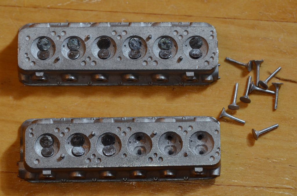
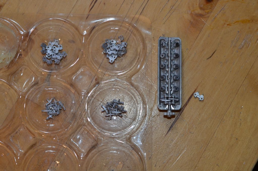
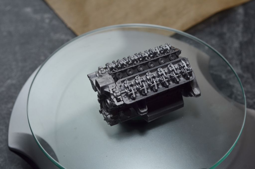
As proposed by the kit's instruction manual, I started with the engine. The special feature of this kit: the cylinders, crankshafts, valves, camshafts, etc. are all modelled separately. Except for the valves, they are all movable and coupled with each other - assuming, that one does not leave a single(!) drop of instant adhesive in the wrong place -> lesson learned ...
It's a pity that you will not see any of this later, unless you show the open engine in a workshop diorama.

The "invisible" parts were a good exercise for me, as this is my first multimedia kit. And I have to say, working with metal parts makes much more fun than with plastic. Sure, it is more effort to clean the parts, deburr them etc. but the big advantage is that only metal looks like real metal. Particularly with the engine no insignificant advantage.
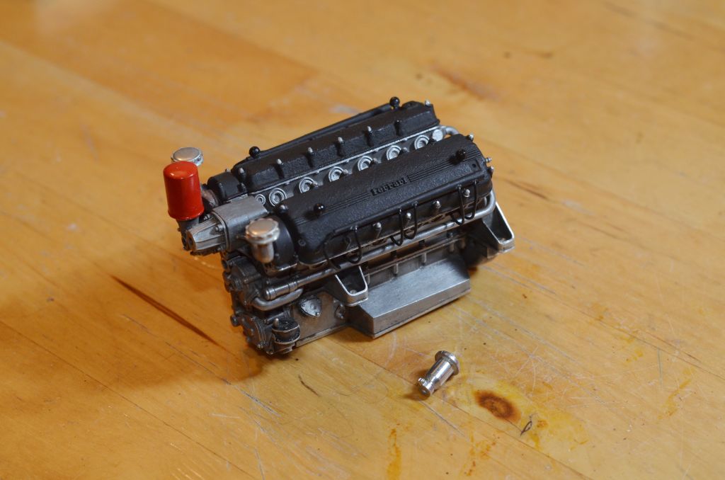
To apply a slight aging to the engine, I painted the metal parts with Armour Wash from Citadel first. After drying, they were cleaned with fine metal fleece so that only "residual dirt" remained on the inner edges and joints. The metal also became a little bit darker overall.
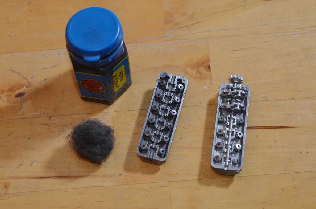
(right: before, left: after)
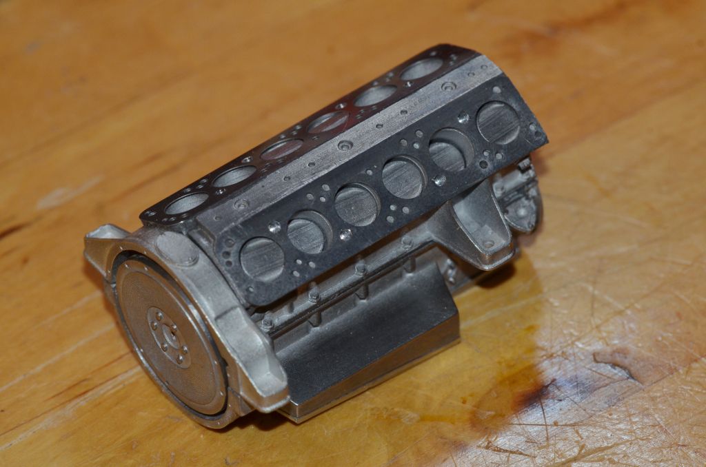
The engine block alone weights 238g. No wonder as it is nearly massive metal.
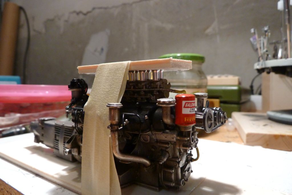
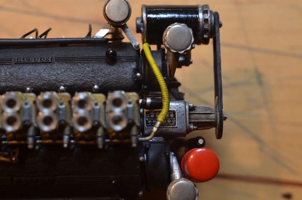
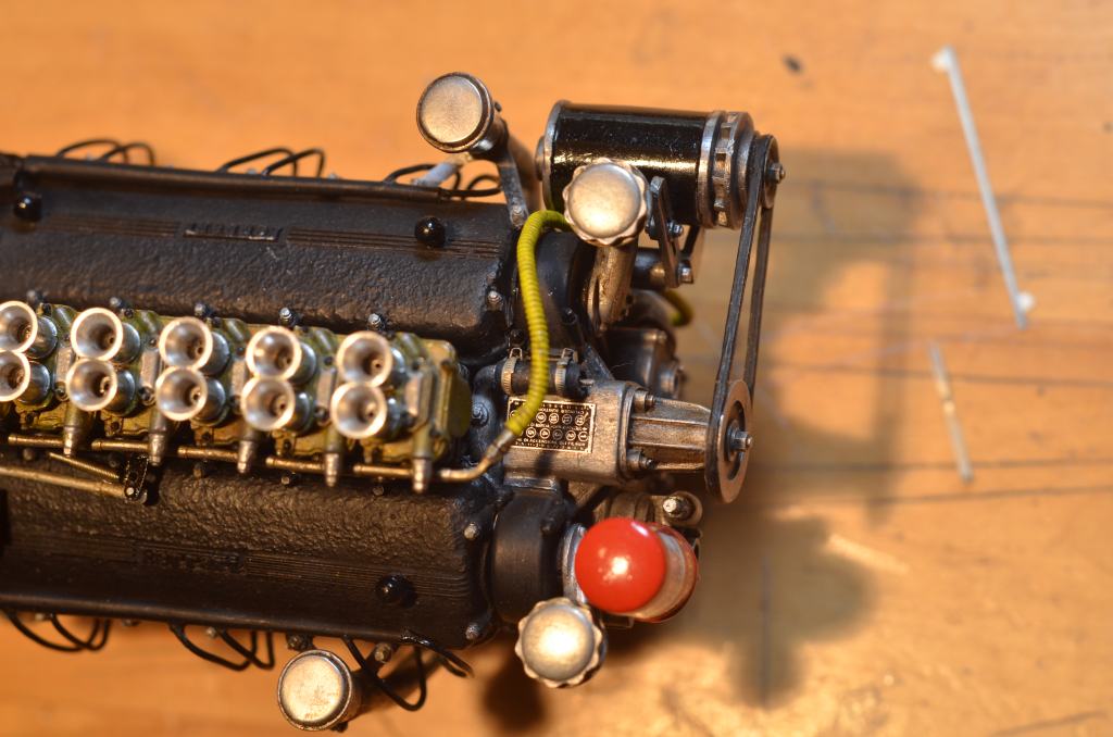
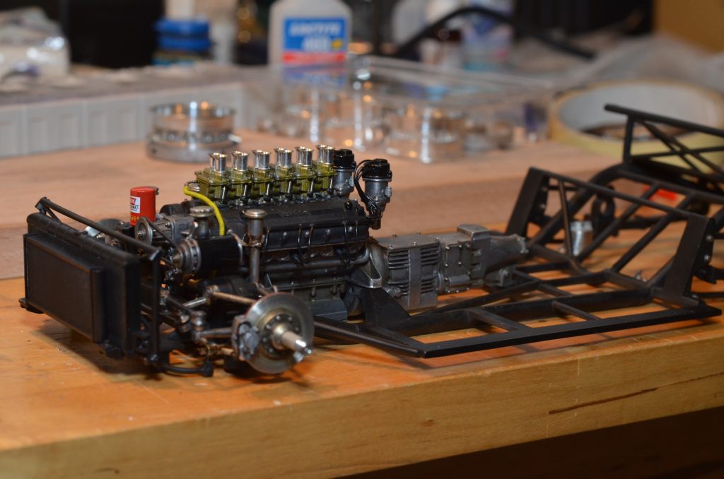
Finally, a picture of the engine with valve covers and a few attachments:
The kit's return springs on the carburettor are realized with photo-etched parts, or let' say "hinted". I have modified these as follows: a thin metal tube is pushed over the photoetching part at the position of the "spring" and the upper end of the photoetching part is rotated by 90°. The metal tube has been treated with abrasive paper while rotated to add slight grooves to imitate the coils of the spring. Afterwards I found a supplier of spring bars in a suitable size. Unfortunately it was too late by then.
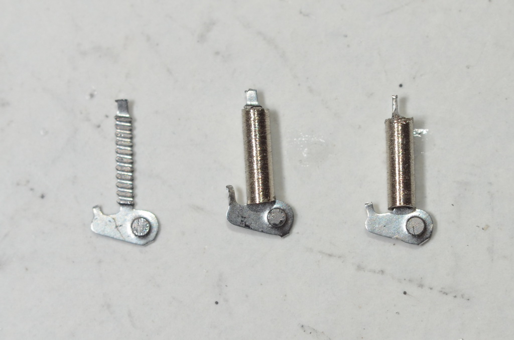
The "hexagon screw" embossed into the photoetch part has been grinded and a hole has been drilled in its place. I placed a bronzed brass screw with washer instead.
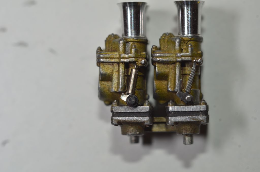
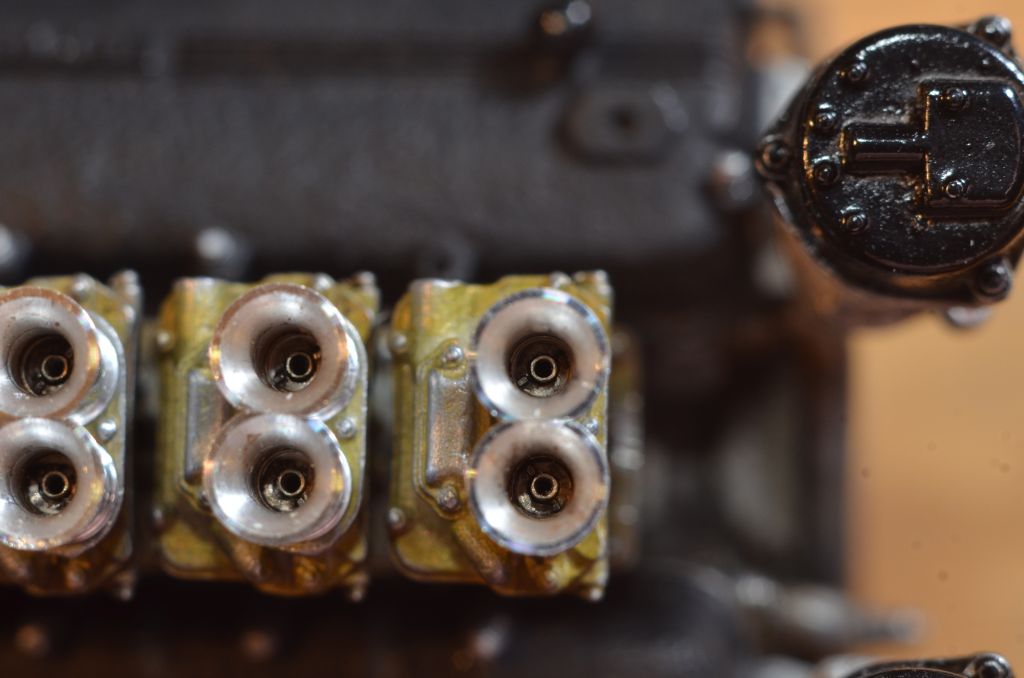
When assembling the carburettors I did some research on the length of the tubes in the middle of the intake funnels. The kit suggests that the tubes go just below the top of the "trumpets". Also various (renowned?) model builders did it this way. However, I cannot follow this based on the original images. Those show quite clearly that the opening protrudes only slightly from the bottom of the intake funnel.
Therefore, I have shortened the tubes. Since one of the tubes vanished from my tweezers and never to be found again, I took the opportunity to replace the enclosed tubes with different ones with a much thinner wall. At the upper end, I additionally drilled up the inner diameter from 0.6mm to 0.7mm (the outer diameter is 0.8mm).
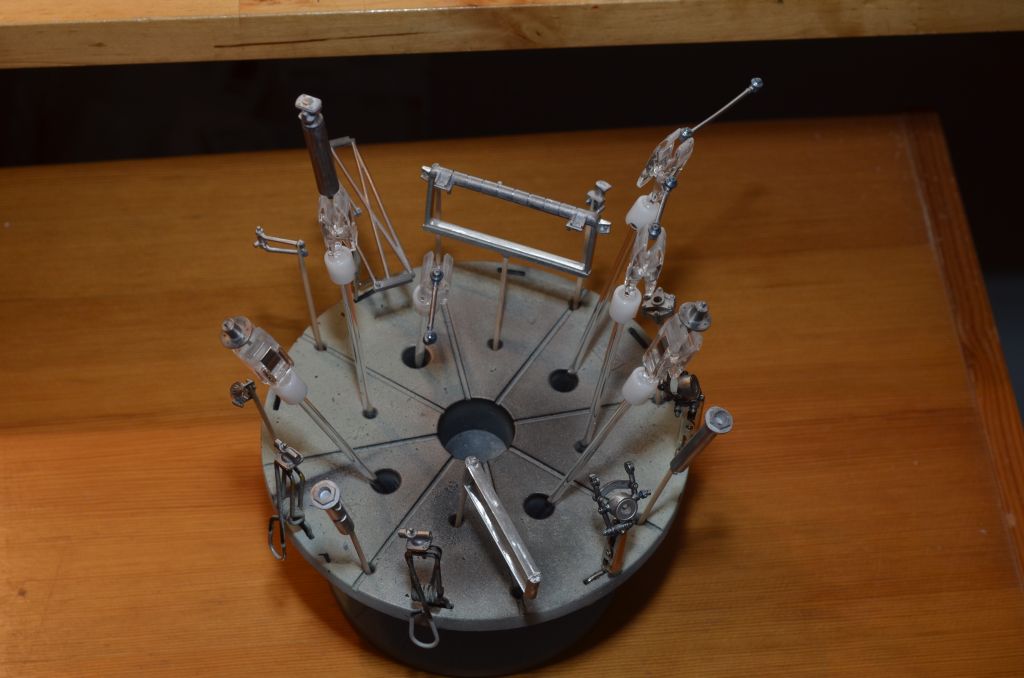
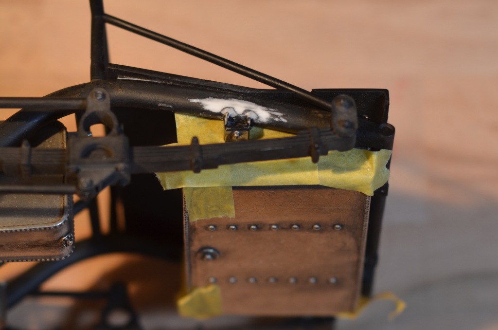
To achieve a proper alignment of the intake funnels I've created a simple auxiliary device and put the cart before the horse.
In a first step I took measurement and transferred the correct position of the intake funnels onto drawing. The drawing has been printed and pasted to a small piece of a wooden board:
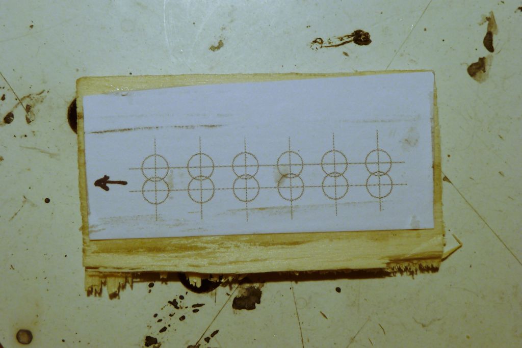
On the drawing I placed transparent double-sided adhesive tape and attached the intake funnels head first onto the drawing. This way, the intake funnels were aligned nicely, all straight and at the same height.
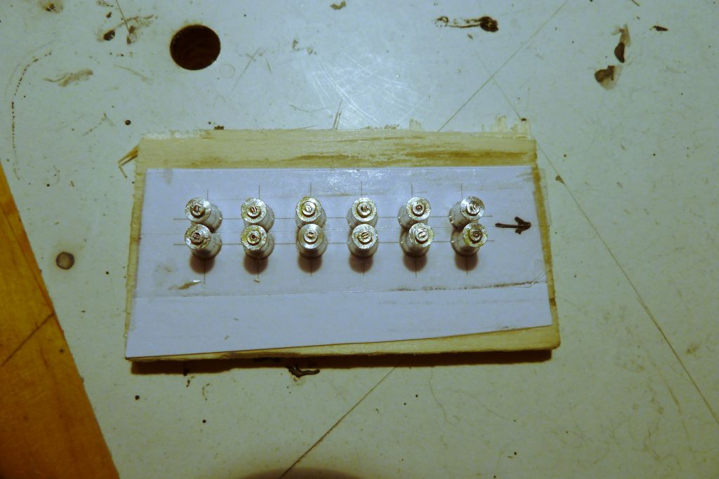
Finally, the whole assembly has been placed on the carburettor and fixed with tape. With a needle I applied small portions of instant adhesive at the gap between the intake funnels and the carburettor.
Pictures of the complete engine can be found in the according album.
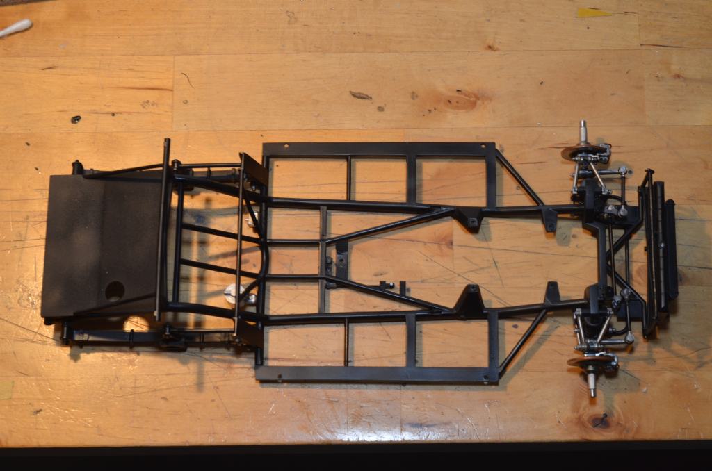
The next phase covers the underbody and the wheel suspension.
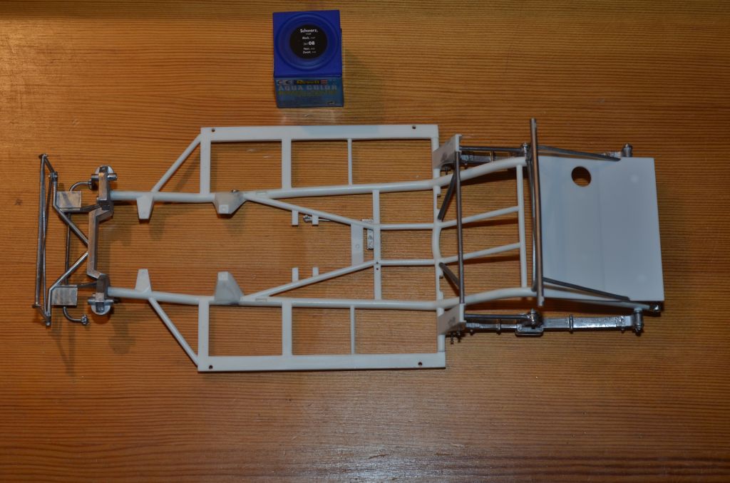
All parts to be painted in semi-gloss black were prepared for priming and subsequent airbrushing.
The areas that are to remain blank are masked with MicroMask.
For the underbody I have pre-assembled all the static semi-gloss black parts, and filled the gaps with putty, where necessary.
The front suspension of the leaf springs has been mounted provisionally with small wire nails, as the final screws will remain blank.
The Revell color pot is included on the photo for comparison only. The parts will be lacquered with Zero Paints.
Before that I have to smooth the resing parts with fine wet sandpaper.
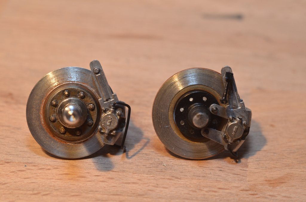
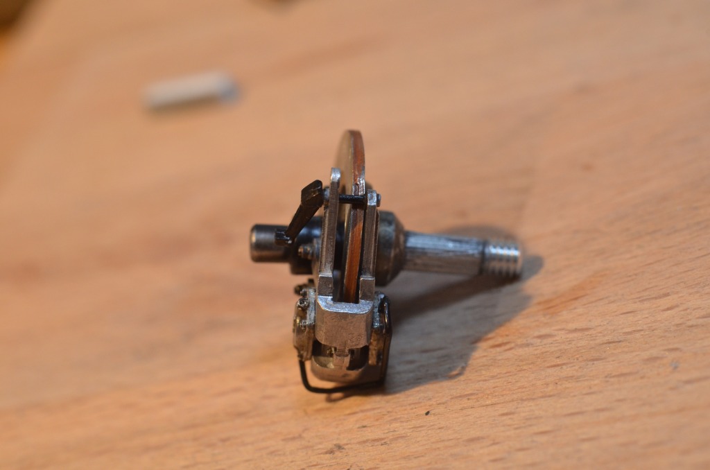
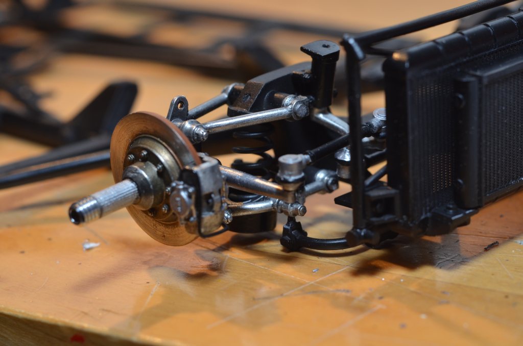
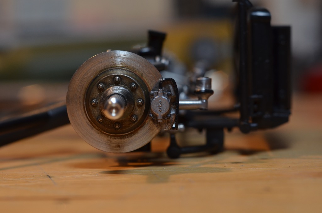
Two pictures of the front disc brakes. My first attempt to add braking grooves was a bit overdone:
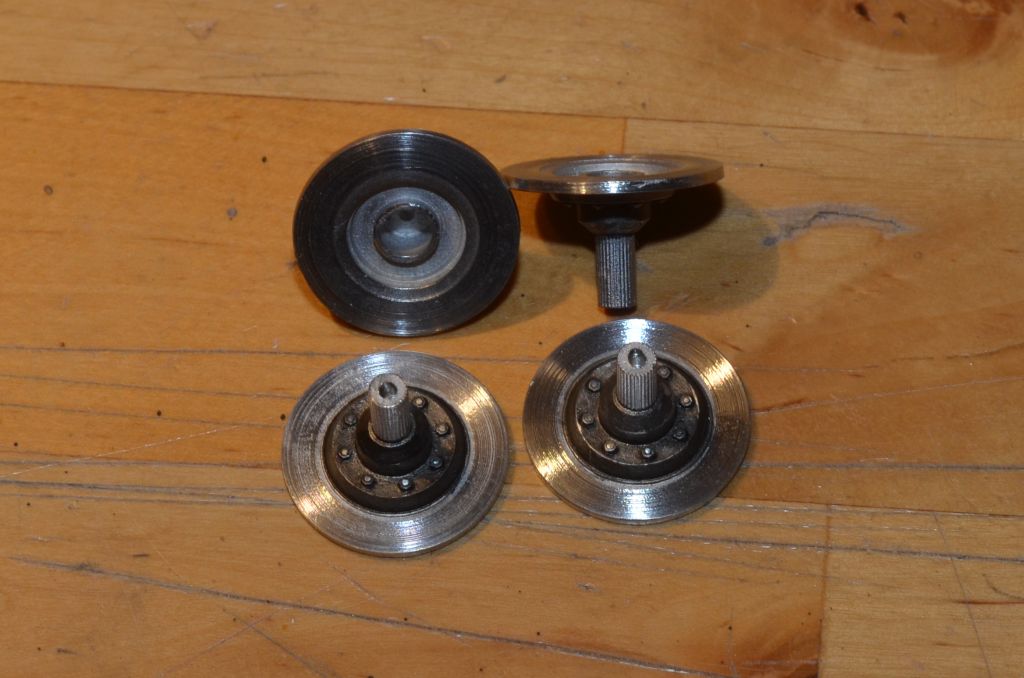
Therefore, I smoothed them a bit again and slighlty aged the discs:
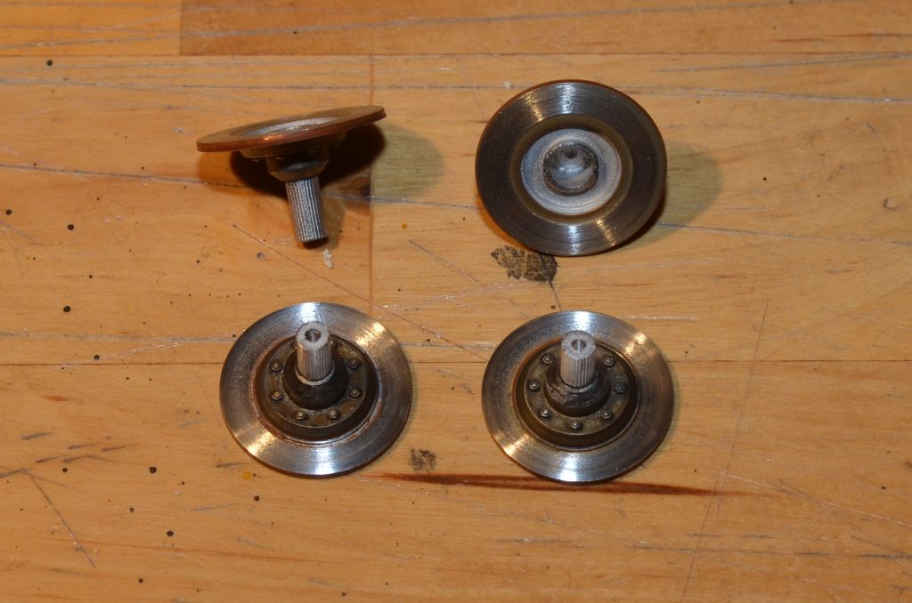
The rear brakes are finised as well:
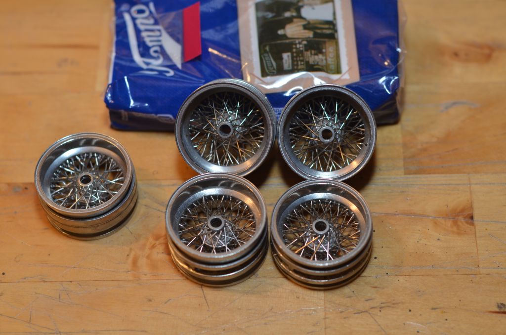
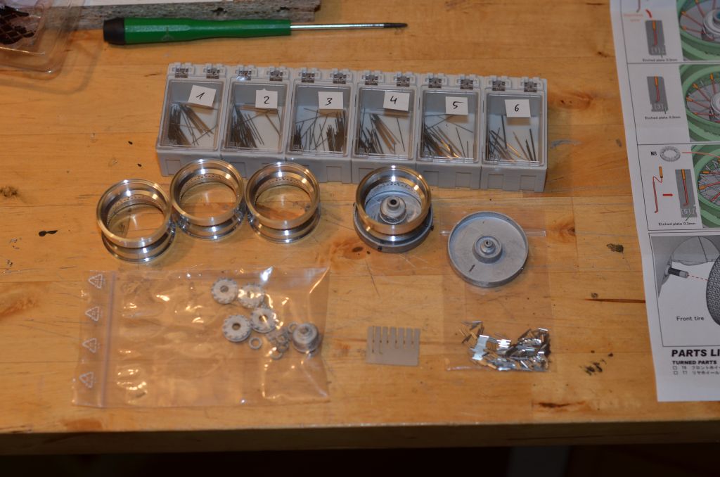
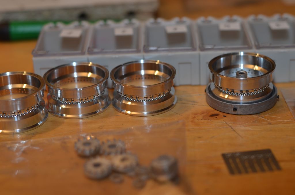
During the preparation of chassis, suspension, etc. I had a look at the spoked wheels. In the first edition (which I build here), the rims and spokes are made of chrome-plated white metal. On the rims I had to make a few drillings. Afterwards, the two inner wheel rim parts are glued together and placed together with the center hub into an assembly device.
The it was step by step: cut the spoke from the casting branch, correct the length, deburr and, if necessary, straighten it and finally place it.
A total of 72 spokes in six levels per wheel. Afterwards the two front and rear rim parts and, of course, the valve will follow.
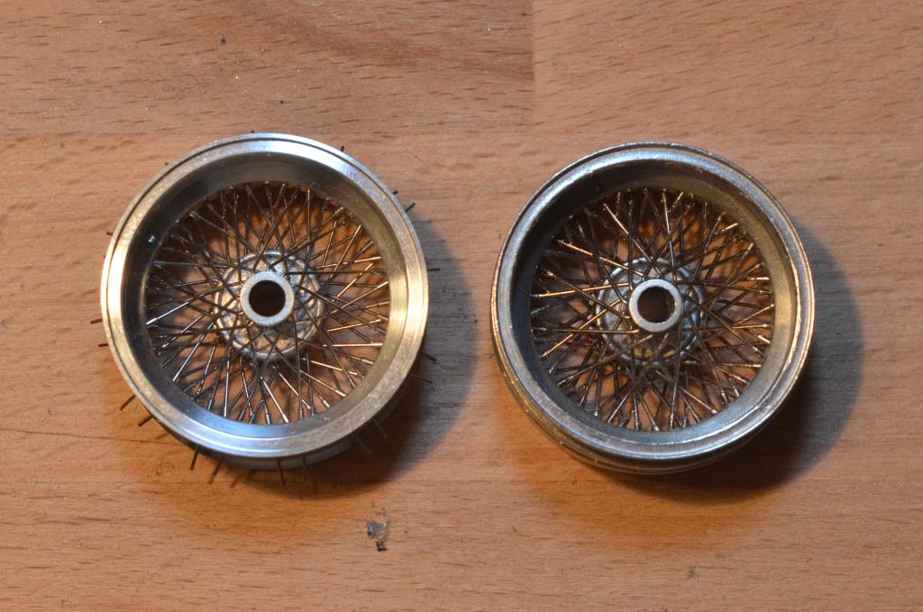
Only the reserve wheel does not consist of individual spokes. Instead, the spokes of one levels are casted as one "disc". It still comes close to the individually spoked wheels (see below).
The spoking of the wheels worked quite well. Everything is well-thoughtout and described. With a bit of practice, you have a wheel ready in 1.5 - 2 hours. Also the result is convincing. At least from afar.
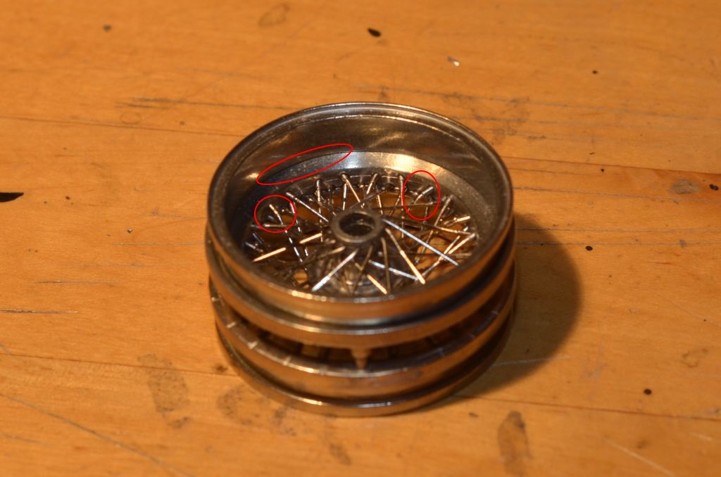
Here we have a direct comparison of the reserve wheel (left) and a separately spoked front wheel (right):
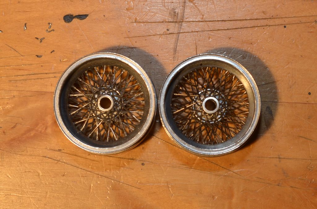
On closer inspection one can find the following weak points:
1. the wheel rim consists of a total of four parts. The gap is well visible at the transition from the inner rim to the outer rim.
2. The slope of the manually applied drill holes cannot be done as steep as required.. As a result, the spokes of the upper wheel rim level are inavitably bent at the transition between narrow and wide sections of the spoke. Difficult to correct this, without risking an irrepealable damage.
3. The length of the cast "sleeves" protruding from the rim is not uniform across all planes
Here is an example for points 1 and 2:
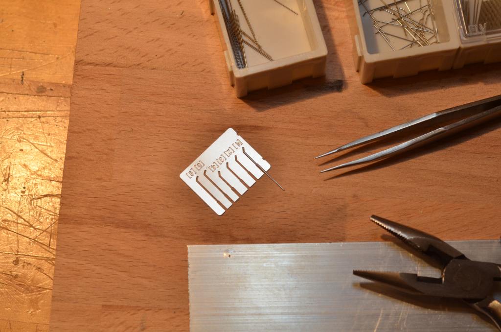
In the succession kit of the 1962 GTO and also in the new edition of this kit the cast spoke wheels were replaced by a higher-quality variant (coming also with an extra charge in costs). Here, the wheel rim consists of a turned and pre-drilled one-piece aluminum element. The spokes are straightened steel wires plus extra sleeves to be attached separately. The steel spokes must be bent at the end according to a photo-etched template. The hub parts and the valve are still of white metal.
This set of spoke wheels is also available as a separate expansion kit:
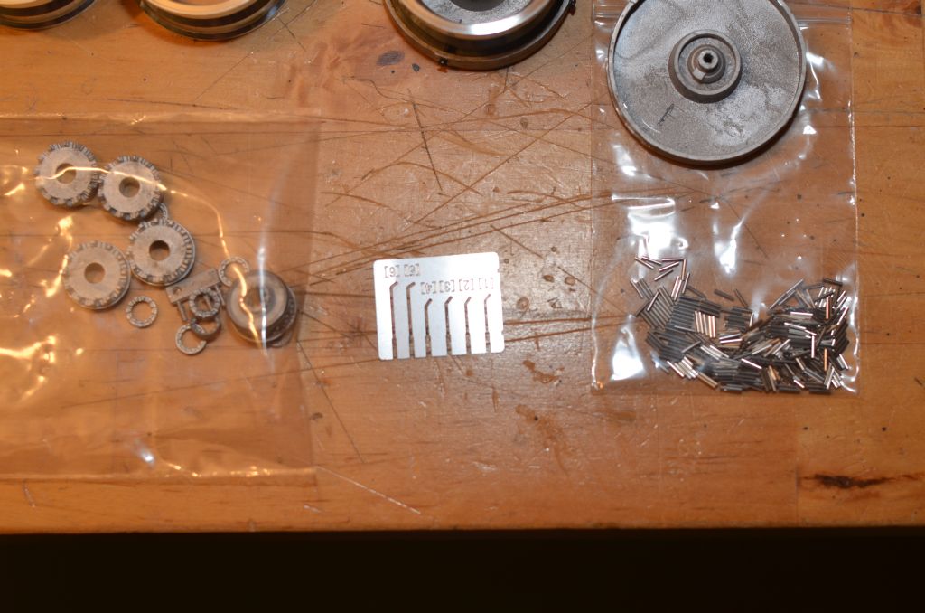
Here you can see a direct comparison of the chromed white metal spokes and the steel spokes with sleeve:
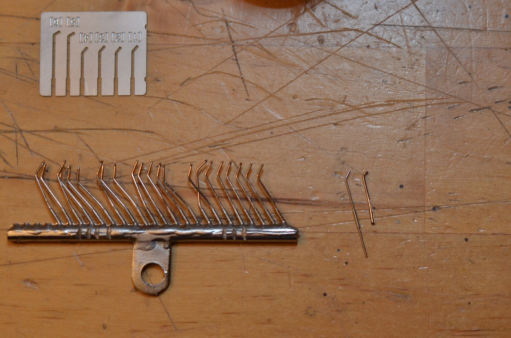
Quite a difference...
The sleeves will be slid onto the spoke after the spokes have been attached to the hub. This way I can ensure that all sleeves are aligned to the rim.
The overlapping steel wires will be cut off after everything has been glued together.
For bending the 288 spokes I created another auxiliary construction:
a 1.6mm and a 1.3mm deep hole with 0.4mm diameter has been drilled into a aluminum slat. The spoke is stuck into the hole and then manually bend at the correct angle. With a bit of practice and routine, the angle will be correct right away. In few cases I had to correct it with a plier.
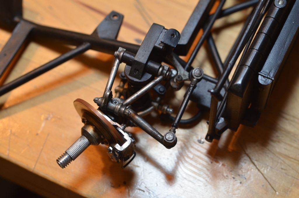
In the meantime the chassis has been lacquered and the front suspension has been assembled:
From underneath:
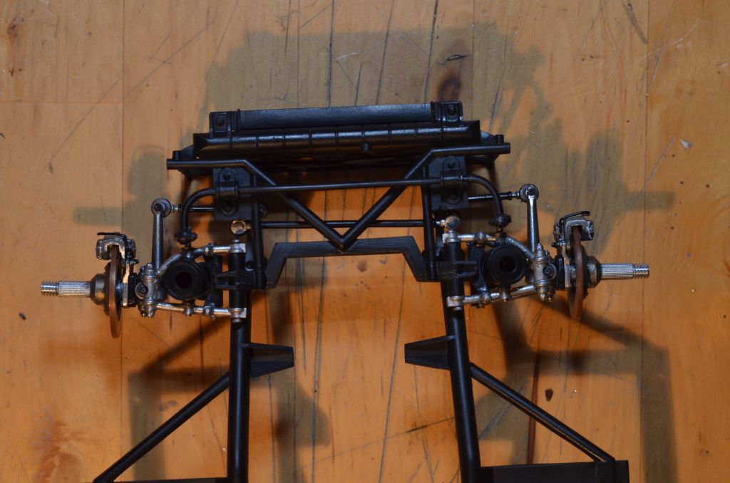
The oil and water radiators haven been assembled as well:

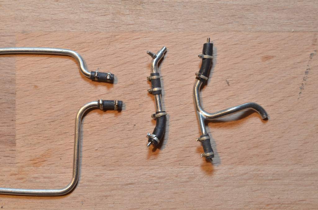
When preparing the tubing between the engine and the radiators I notec another minor flaw of the kit.
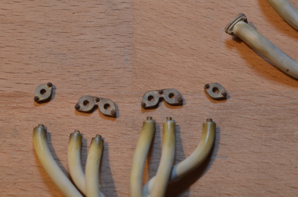
The "thickening" cast onto the following parts are in real life hoses with hose clamps:
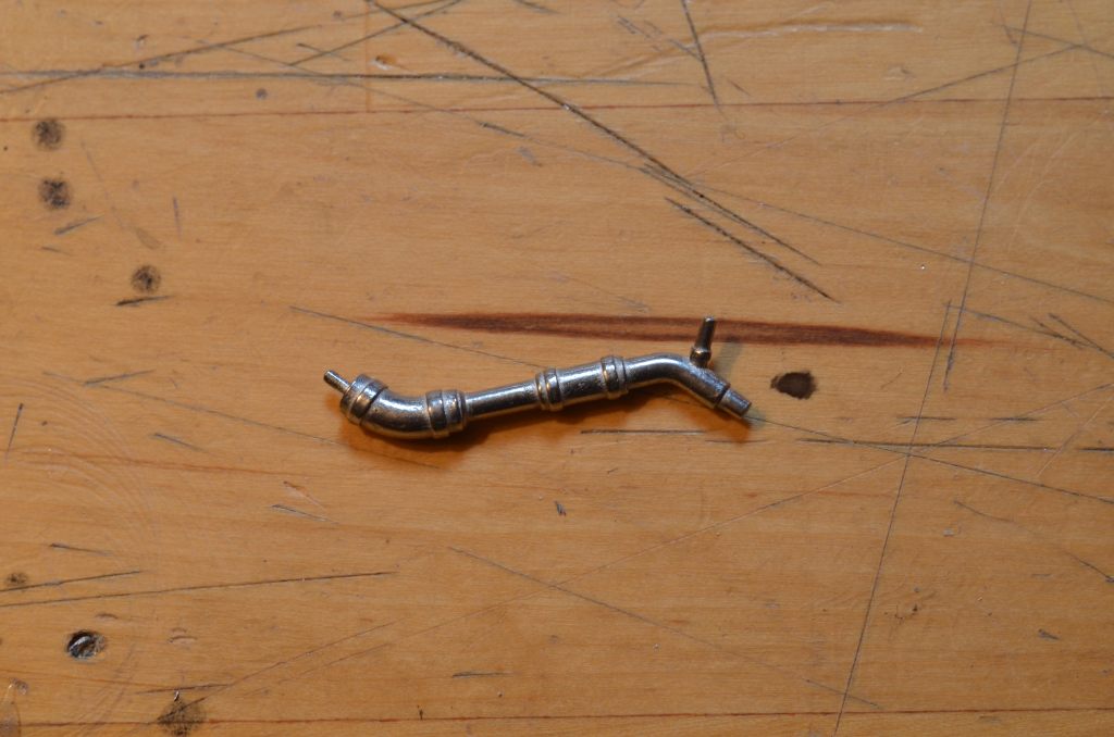
In the kit it is only foreseen to paint the hose part in matt black. This can be done better!
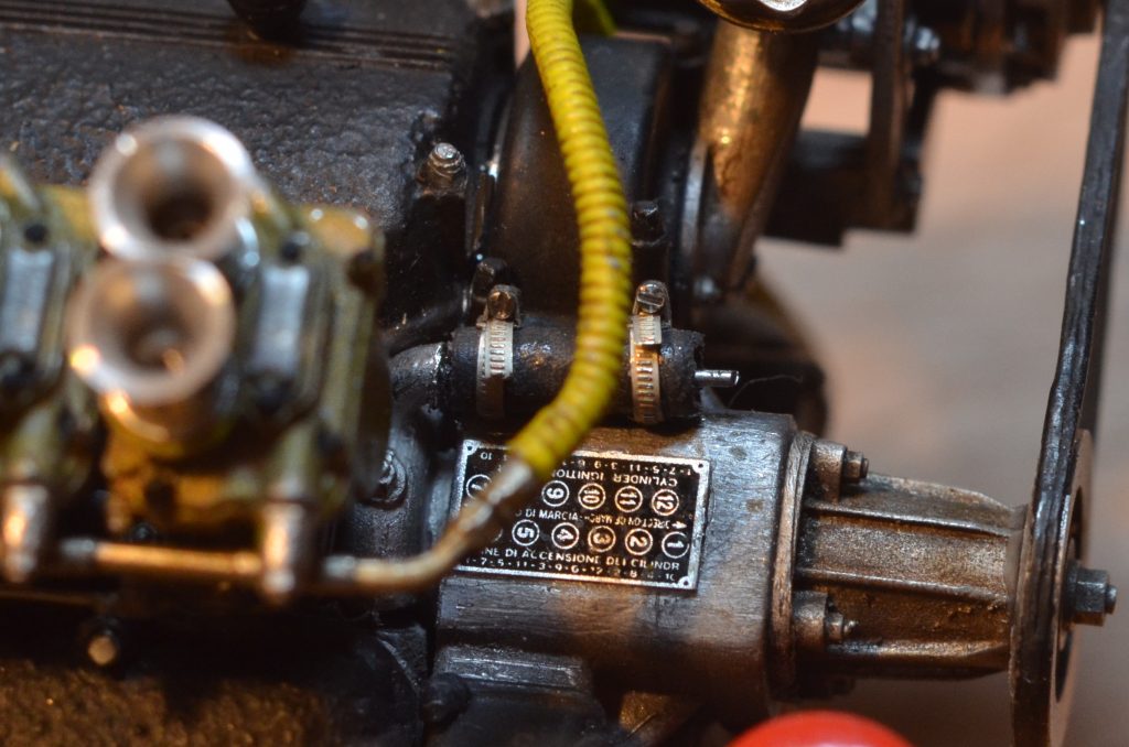
So I grinded the thickend parts, added heat shrink tube and miniatur hose clamps.
Unfortunately I had to notice, that one of these parts has already been assembled to the engine block, where it is no longer accessible.
This is how the original part looks like, if it painted:
And this how it looks like after removing it and scratch-building a new part:
And now with tiny screws for the hose clamps:
The remaining tubing is processed the same way:
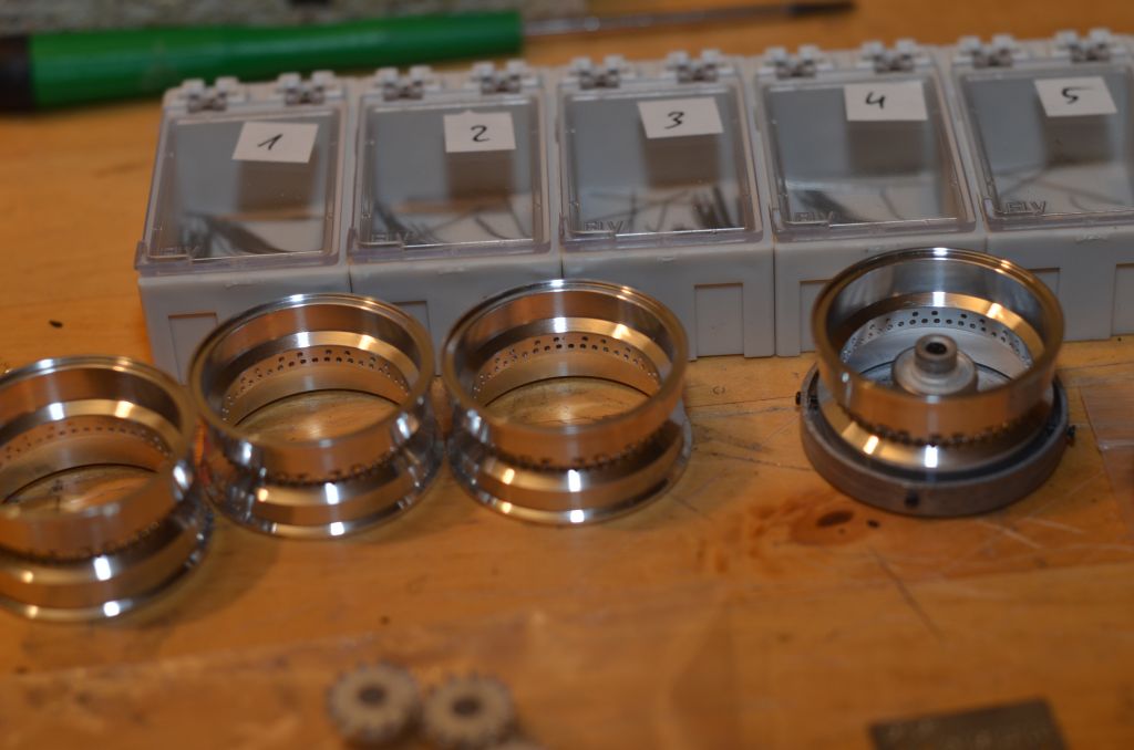
The first spoke wheel from the expansion kit is ready.
It's significantly more work to assemble the steel spokes, but it was worth the effort.
The new wheels leave a much more consistent and filigree impression.
The remaining protruding steel wires still have to be cut
The finally assembled new spoke wheels:
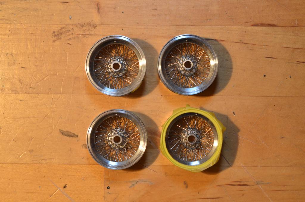
One wheel is already masked for the transparent blue lacquer from the Maranello Concessionaires.
But this will be tested first with one of the old wheels from the original kit.
The chassis and suspension has been aged slightly
Like with the engine, no real dirt, just the usual signs of wear.
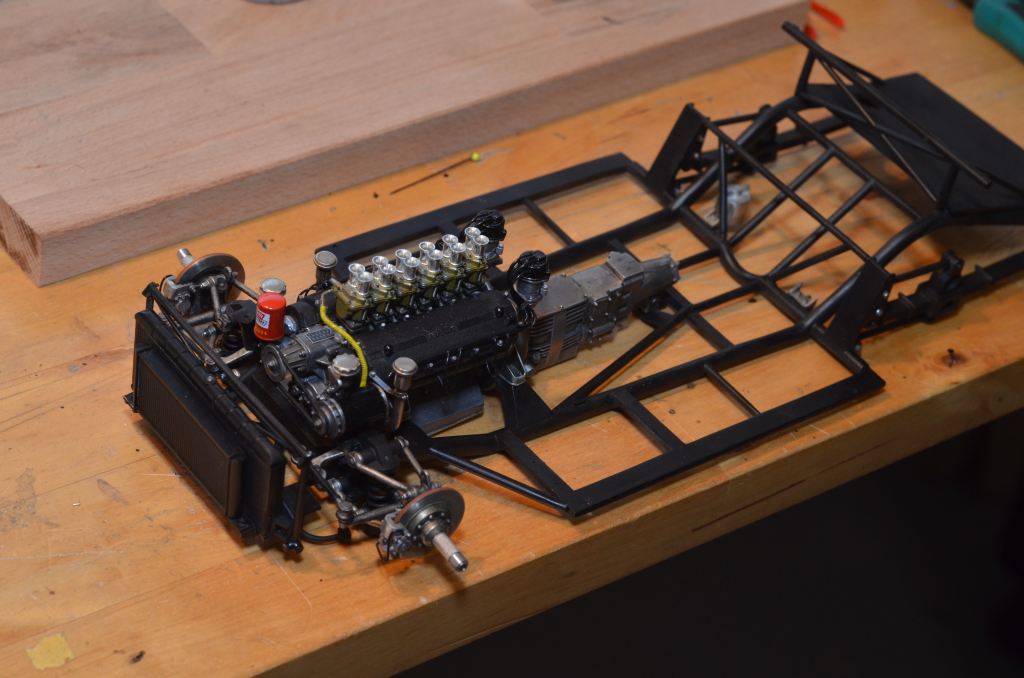
Following this I tested the "marriage" of engine and chassis:
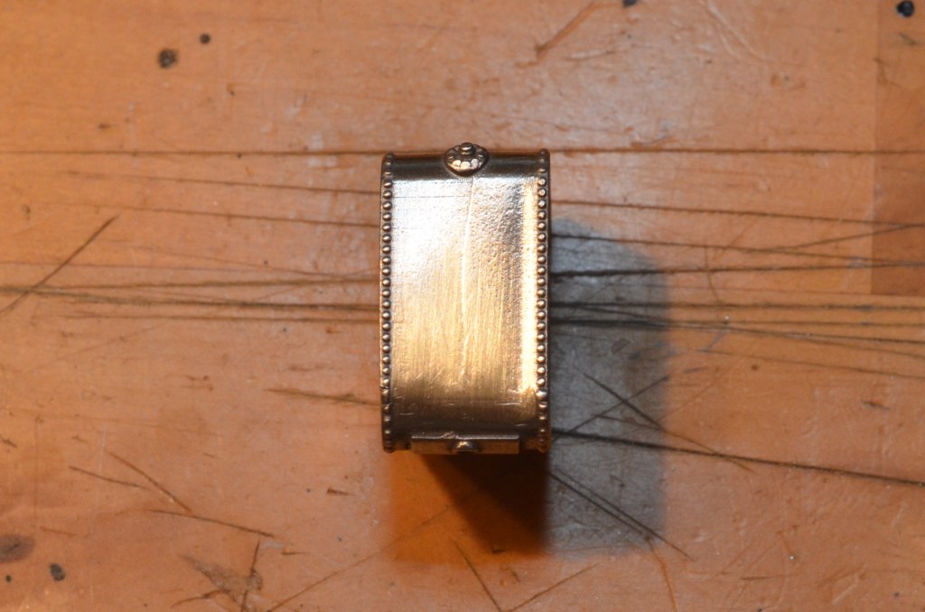
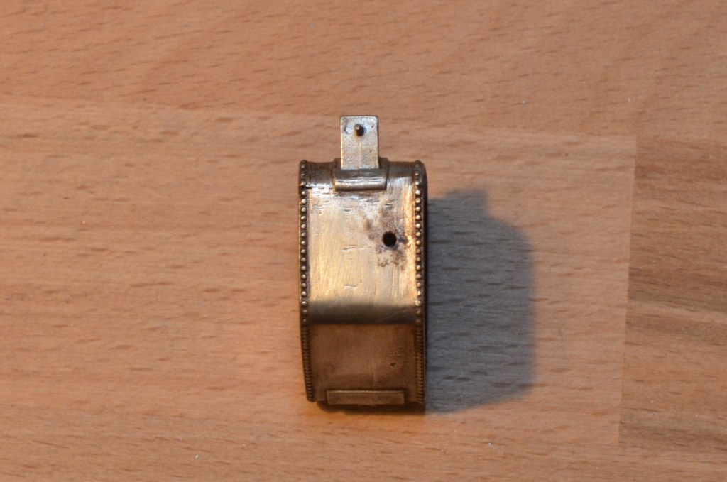
Next I focused on the fuel and oil tank
They consist of two white metal parts each. Unfortunately, there is a significant gap at the abutting edges, like seen here at the fuel tank:
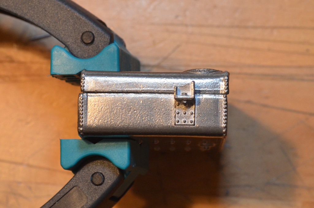
So I heated up my soldering iron, grabbed the low temperatur soldering tin (65°) and filled in the gap (top side):
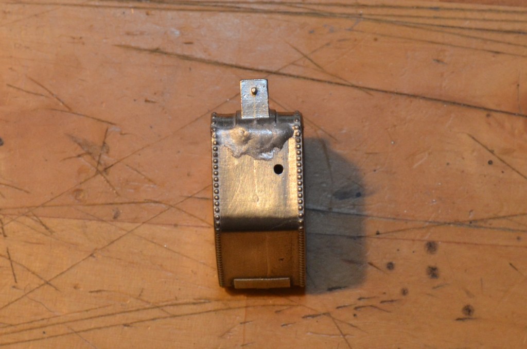
The bottom part after grinding and polishing:
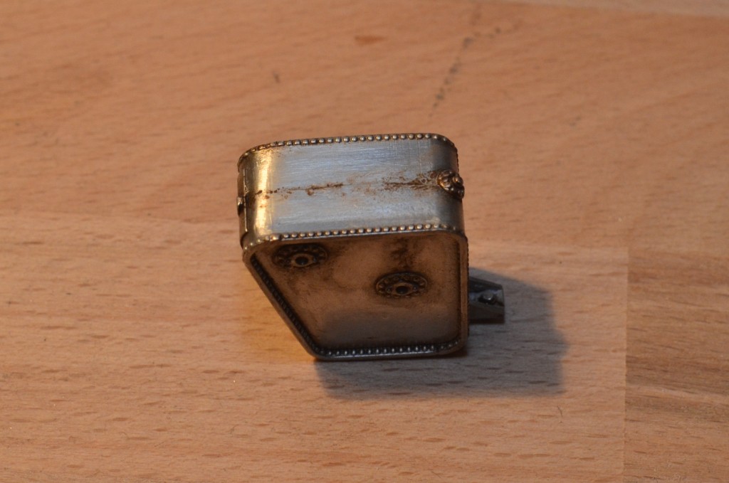
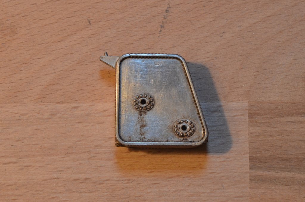
And of course the oil tank also needs some aging:
The gap at the carrier of the fuel and the chassis had to be closed with putty.
Repainting will be done on next occasion.
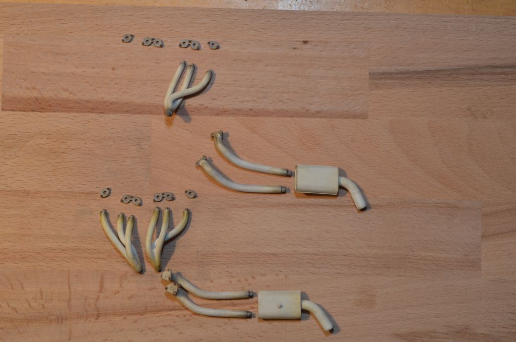
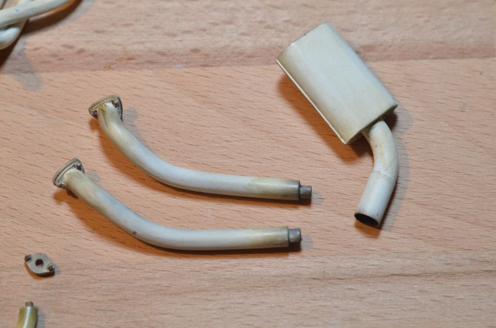
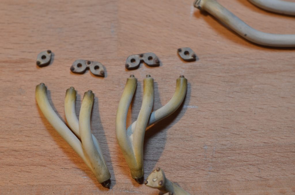
Next step is the exhaust system, which is painted in matt white.
I experimented a bit with different ways of aging, by applying oil color, pastel chalk and Tamiya Weathering Set D (Burning):
To be continued...